Powered By

Free XML Skins for Blogger

Powered by Blogger

Wednesday, June 4, 2008

MOTHER BOARD

A motherboard is the central or primary printed circuit board (PCB) making up a complex electronic system, such as a modern computer. It is also known as a mainboard, baseboard, system board, planar board, or, on Apple computers, a logic board, and is sometimes abbreviated casually as mobo.

Most motherboards produced today are designed for so-called IBM-compatible computers, which held over 96% of the global personal computer market in 2005. Motherboards for IBM-compatible computers are specifically covered in the PC motherboard article.

A motherboard, like a backplane, provides the electrical connections by which the other components of the system communicate, but unlike a backplane also contains the central processing unit and other subsystems such as real time clock, and some peripheral interfaces.

A typical desktop computer is built with the microprocessor, main memory, and other essential components on the motherboard. Other components such as external storage, controllers for video display and sound, and peripheral devices are typically attached to the motherboard via edge connectors and cables, although in modern computers it is increasingly common to integrate these "peripherals" into the motherboard.

Components and functions

The 2004 K7VT4A Pro motherboard by ASRock.  The chipset on this board consists of northbridge and southbridge chips.

The 2004 K7VT4A Pro motherboard by ASRock. The chipset on this board consists of northbridge and southbridge chips.

The motherboard of a typical desktop consists of a large printed circuit board. It holds electronic components and interconnects, as well as physical connectors (sockets, slots, and headers) into which other computer components may be inserted or attached.

Most motherboards include, at a minimum:

  • sockets (or slots) in which one or more microprocessors (CPUs) are installed
  • slots into which the system's main memory is installed (typically in the form of DIMM modules containing DRAM chips)
  • a chipset which forms an interface between the CPU's front-side bus, main memory, and peripheral buses
  • non-volatile memory chips (usually Flash ROM in modern motherboards) containing the system's firmware or BIOS
  • a clock generator which produces the system clock signal to synchronize the various components
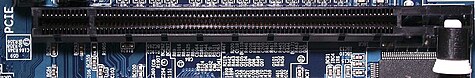
  • slots for expansion cards (these interface to the system via the buses supported by the chipset)
  • power connectors and circuits, which receive electrical power from the computer power supply and distribute it to the CPU, chipset, main memory, and expansion cards.
The Octek Jaguar V motherboard from 1993. This board has 6 ISA slots but few onboard peripherals, as evidenced by the lack of external connectors.

The Octek Jaguar V motherboard from 1993.This board has 6 ISA slots but few onboard peripherals, as evidenced by the lack of external connectors.

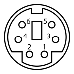
Additionally, nearly all motherboards include logic and connectors to support commonly-used input devices, such as PS/2 connectors for a mouse and keyboard. Early personal computers such as the Apple II or IBM PC included only this minimal peripheral support on the motherboard. Occasionally video interface hardware was also integrated into the motherboard; for example on the Apple II, and rarely on IBM-comatible computers such as the IBM PC Jr. Additional peripherals such as disk controllers and serial ports were provided as expansion cards.

Given the high thermal design power of high-speed computer CPUs and components, modern motherboards nearly always include heatsinks and mounting points for fans to dissipate excess heat.

Integrated peripherals

Diagram of a modern motherboard, which supports many on-board peripheral functions as well as several expansion slots.

Diagram of a modern motherboard, which supports many on-board peripheral functions as well as several expansion slots.

With the steadily declining costs and size of integrated circuits, it is now possible to include support for many peripherals on the motherboard. By combining many functions on one PCB, the physical size and total cost of the system may be reduced; highly-integrated motherboards are thus especially popular in small form factor and budget computers.

For example, the ECS RS485M-M, a typical modern budget motherboard for computers based on AMD processors, has on-board support for a very large range of peripherals:

  • disk controllers for a floppy disk drive, up to 2 PATA drives, and up to 6 SATA drives (including RAID 0/1 support)
  • integrated ATI Radeon graphics controller supporting 2D and 3D graphics, with VGA and TV output
  • integrated sound card supporting 8-channel (7.1) audio and S/PDIF output
  • fast Ethernet network controller for 10/100 Mbit networking
  • USB 2.0 controller supporting up to 12 USB ports
  • IrDA controller for infrared data communication (e.g. with an IrDA enabled Cellular Phone or Printer)
  • temperature, voltage, and fan-speed sensors that allow software to monitor the health of computer components

Expansion cards to support all of these functions would have cost hundreds of dollars even a decade ago, however as of April 2007 such highly-integrated motherboards are available for as little as $30 in the USA.

Temperature and reliability

Motherboards are generally air cooled with heat sinks often mounted on larger chips, such as the northbridge, in modern motherboards. Passive cooling, or a single fan mounted on the power supply, was sufficient for many desktop computer CPUs until the late 1990s; since then, most have required CPU fans mounted on their heatsinks, due to rising clock speeds and power consumption. Most motherboards have connectors for additional case fans as well. Newer motherboards have integrated temperature sensors to detect motherboard and CPU temperatures, and controllable fan connectors which the BIOS or operating system can use to regulate fan speed.

Some small form factor computers and home theater PCs designed for quiet and energy-efficient operation boast fan-less designs. This typically requires the use of a low-power CPU, as well as careful layout of the motherboard and other components to allow for heat sink placement.

A 2003 study found that some spurious computer crashes and general reliability issues, ranging from screen image distortions to I/O read/write errors, can be attributed not to software or peripheral hardware but to aging capacitors on PC motherboards. Ultimately this was shown to be the result of a faulty electrolyte formulation.


Motherboards use electrolytic capacitors to filter the DC power distributed around the board. These capacitors age at a temperature-dependent rate, as their water based electrolytes slowly evaporate. This can lead to loss of capacitance and subsequent motherboard malfunctions due to voltage instabilities. While most capacitors are rated for 2000 hours of operation at 105 °C,[10] their expected design life roughly doubles for every 10 °C below this. At 45 °C a lifetime of 15 years can be expected. This appears reasonable for a computer motherboard, however many manufacturers have delivered substandard capacitors, which significantly reduce this life expectancy. Inadequate case cooling and elevated temperatures easily exacerbate this problem. It is possible, but tedious and time-consuming, to find and replace failed capacitors on PC motherboards; it is less expensive to buy a new motherboard than to pay for such a repair.

History

Prior to the advent of the microprocessor, a computer was usually built in a card-cage case or mainframe with components connected by a backplane consisting of a set of slots themselves connected with wires; in very old designs the wires were discrete connections between card connector pins, but printed-circuit boards soon became the standard practice. The central processing unit, memory and peripherals were housed on individual printed circuit boards which plugged into the backplane.

During the late 1980s and 1990s, it became economical to move an increasing number of peripheral functions onto the motherboard (see above). In the late 1980s, motherboards began to include single ICs (called Super I/O chips) capable of supporting a set of low-speed peripherals: keyboard, mouse, floppy disk drive, serial ports, and parallel ports. As of the late 1990s, many personal computer motherboards support a full range of audio, video, storage, and networking functions without the need for any expansion cards at all; higher-end systems for 3D gaming and computer graphics typically retain only the graphics card as a separate component.

The early pioneers of motherboard manufacturing were Micronics, Mylex, AMI, DTK, Hauppauge, Orchid Technology, Elitegroup, DFI, and a number of Taiwan-based manufacturers.

Popular personal computers such as the Apple II and IBM PC had published schematic diagrams and other documentation which permitted rapid reverse-engineering and third-party replacement motherboards. Usually intended for building new computers compatible with the exemplars, many motherboards offered additional performance or other features and were used to upgrade the manufacturer's original equipment.

Bootstrapping using the BIOS

Motherboards contain some non-volatile memory to initialize the system and load an operating system from some external peripheral device. Microcomputers such as the Apple II and IBM PC used read-only memory chips, mounted in sockets on the motherboard. At power up the central processor would load its program counter with the address of the boot ROM and start executing ROM instructions displaying system information on the screen and running memory checks, which would in turn start loading memory from an external or peripheral device (disk drive) if one isn't available then the computer can perform tasks from other memory stores or displays an error message depending on the model and design of the computer and version of the bios.


Most modern motherboard designs use a BIOS, stored in a EEPROM chip soldered to the motherboard, to bootstrap the motherboard. (Socketed BIOS chips are widely used, also.) By booting the motherboard, the memory, circuitry, and peripherals are tested and configured. This process is known as a Power On Self Test or POST. Errors during POST result in POST error codes, ranging from simple audible beeps from the speaker to complex diagnostic messages displayed on the video monitor.

The BIOS often requires configuration settings to be stored on the motherboard. Since configuration settings must be easily edited, these settings are often stored in non-volatile RAM (NVRAM) rather than in some sort of read-only memory (ROM). When a user makes configuration changes or alters the date and time of the computer, this small NVRAM circuit stores the data. Typically, a small, long-lasting battery (e.g. a lithium coin cell CR2032) is used to keep the NVRAM "refreshed" for many years. Therefore, a failing battery on a motherboard will produce the symptoms of a computer that cannot determine the correct date and time, nor remember what hardware configuration the user has selected. The BIOS itself is unaffected by the status of the battery.

When IBM first introduced the PC in the 1980s, imitations were quite common. (The physical parts which made up the motherboard were trivial to acquire.) However, the imitations were never successful until the IBM ROM BIOS was legally copied. To understand why copying the BIOS was an important step, consider that the BIOS contained vital instructions which interacted with peripherals. Without these software instructions in the BIOS, a PC would not function properly. (In most modern computer operating systems, the BIOS is bypassed for most hardware functions, but in the 1980s, the BIOS served many vital low-level functions.)

So when Compaq Computer Corp. spent US$1 million to clone the IBM BIOS using reverse engineering, they became an elite computer manufacturer of IBM PC Clones. Phoenix Technology soon matched their feat and began reselling BIOSes to other clone makers. It has been noted that Microsoft was more than happy to license the operating system (DOS), and IBM was more than happy to sue companies that violated the copyright of their BIOS. But by documenting and publicizing the reverse engineering of the BIOS, Compaq and Phoenix were legally competing with IBM using their own copyrighted BIOS.

Once the bootstrapping of the computer's peripherals are complete, the BIOS will normally pass control to another set of instructions stored on a bootable device.

Devices which are normally used to boot a computer:

  • floppy drive
  • network controller
  • CD-ROM drive
  • DVD-ROM drive
  • SCSI hard drive
  • IDE, EIDE, or SATA hard drive
  • External USB memory storage device

Any of the above devices can be stored with machine code instructions to load an operating system or a program.

Form factors

Motherboards are produced in a variety of sizes and shapes ("form factors"), some of which are specific to individual computer manufacturers. However, the motherboards used in IBM-compatible commodity computers have been standardized to fit various case sizes. As of 2007, most desktop computer motherboards use one of these standard form factors—even those found in Macintosh and Sun computers which have not traditionally been built from commodity components.

Laptop computers generally use highly integrated, miniaturized, and customized motherboards. This is one of the reasons that laptop computers are difficult to upgrade and expensive to repair. Often the failure of one laptop component requires the replacement of the entire motherboard, which is usually more expensive than a desktop motherboard due to the large number of integrated components.

  • Chipset: The chipset is the core logic of the motherboard and is responsible for most of its characteristics. After form factor, this is a primary differentiator of different motherboards, as the chipset is key to what CPUs, memory types, and other peripherals the motherboard will support. Intel is a prime designer and maker of chipsets, normally supporting its own CPUs of course; for non-Intel CPUs you will be looking at non-Intel chipsets. At one time Intel chipsets utterly dominated the market, but the situation is more balanced now, with a number of other manufacturers such as Via and ALi taking increasing market share of both OEM systems and retail motherboard sales.
  • CPU Support: The chipset must support the particular CPU you want to use, or allow you a choice you will be happy with. CPU support is a function of the chipset choice, the bus speed and multiplier settings provided on the board, the voltage levels provided on the board, and also compatibility from the system BIOS. Support for additional CPUs sometimes comes from BIOS upgrades. CPU support may be specified by listing particular CPUs, or by specifying the CPU interface (slot or socket type) that the motherboard implements.
    Note that in some cases there are compatibility lists for particular platforms, especially for non-Intel CPUs. These are lists of specific boards that have been tested and approved for use with the CPU in question. It's a good idea to try to get a board on the list if it is applicable. Check the CPU maker's web site for assistance.
  • Video Support: The video card either goes into a slot on the motherboard, or its functionality is integrated onto it. Most modern systems use AGP video, so you will want to look for an AGP slot on the board. There are different levels of AGP support: newer boards will support faster modes such as 4X AGP and AGP Pro, as well as older cards. If you are upgrading and using an older PCI video card then plan on using a PCI slot for it (I am not even going to mention ISA video--scary! :^) ).
  • Memory Support: Motherboards vary in terms of the number of memory slots they provide, and also what sizes and types of modules are supported. While today this is fairly universal between brands, check carefully, especially if you want to run a lot of memory (256 MiB or more). Note that motherboards also vary in terms of the speed of the memory bus, but this is tied to some extent to the choice of CPU and chipset.
  • System Bus Types And Number: Motherboards differ greatly in terms of the number of system bus slots they support. This is often a function of board size: smaller boards usually have fewer slots. If you are planning a system that will have many expansion devices, be sure the motherboard has enough of the right types of slots. If you are upgrading, pay special attention, especially if you need ISA slots, as they are becoming harder to find today.

Note: A common design is to share two slots of different types; you can use one or the other of that set. If you see a specification such as "1 AGP, 4 PCI, 2 ISA (1 shared)", this means that one PCI and one ISA slot are right next to each other; only one of that pair can be used. So this board can use 1 AGP slot (for the video card), and either 4 PCI and 1 ISA, or 3 PCI and 2 ISA. (Sometimes one PCI and one ISA are shared and they don't mention this--assume it unless you can verify otherwise.)

Performance and Capacity Selection Criteria: There are a few issues that most motherboard buyers look for in terms of their impact on overall system performance and capacity issues. Mostly, performance of the system isn't a function of the motherboard but the other hardware it supports and works with (see the discussion of performance impact further down). You may want to look for these when shopping, however:

  • IDE/ATA Controller: The interface controller for the hard disk and other IDE/ATA compatible drives is built into the chipset on most boards. Some have support for higher interface transfer speeds.
  • RAID: Some newer motherboards are now coming with support for software RAID on their integrated disk controllers. While certainly not high on the list of performance RAID implementations, this may be of appeal to some.
  • Multiple CPU Support: Some motherboards support the use of multiple processors (when used with capable CPUs and suitable operating systems and application software).
  • Memory Capacity: The number of slots provided on the board and how much each can hold limits total usable memory and expandability, and memory is certainly very important to performance, especially on high-end systems.
  • I/O Interfaces: Almost all modern motherboards come with support for at least the following: two serial ports, one parallel port, one keyboard port, and one PS/2 mouse port. Most also now come with two USB ports, which are close to being essential in today's peripheral market. Some come with other interfaces such as a game port for a joystick or other game controller.
  • Overclockability: If you plan to overclock your system, you'll want to pay attention to reviews that assess different motherboards in terms of how much they facilitate system overclocking.
  • System Cache Type And Amount: Most modern PCs now have their secondary cache integrated into the physical processor package, but older designs (primarily for the 486, original Pentium, and compatible non-Intel CPUs) use cache on the motherboard. The amount of cache has an impact on overall performance, though it isn't enormous.

Quality Selection Criteria: As a key system component, the quality of the motherboard is very important, and often overlooked. As someone who recently spent weeks diagnosing a flaky system that turned out to be a result of a bad motherboard, let me assure you that motherboard quality is essential. :^) Note that some manufacturers, and some models, have generally better reputations for quality and stability than others. Of course you're not going to be able to find this out by asking the manufacturers. :^) Rely on advice from those you trust and a general sense of who has success with what makers based on your research. When assessing quality, look at the following factors:

  • Stability and Reliability: For my money, this is the most important characteristic of any motherboard: reliable, stable operation. You will need to research others' experiences to judge this, and also assess the past history of the company.
  • Layout: Motherboards vary greatly in terms of how the various components are laid out. Better layouts space components to prevent crowding or interference, and make it easier to build the system. Look for comments from those who have installed a board in the past: did they have a difficult time? In general, bigger boards are better than smaller ones in this regard. Look especially for support components crowded around the CPU slot or socket that might interfere with CPU heat sinks or fans.
  • Rigidity and Construction: Better boards are thicker and stronger than cheap ones.
  • Accessory Set: Be sure that the motherboard includes a full set of needed accessories, such as floppy and IDE/ATA cables, driver disks, retention module for the CPU (if appropriate) and so on. (These are usually included in retail-packaged boards; see below).
  • Manual and Online Documentation: The motherboard manual is an essential aid in setting up your system; assess its quality, as well as the quality of supplemental documentation such as that provided by the manufacturer's web site.
  • ECC Memory Support: For the best reliability and stability, look for a motherboard that works with ECC memory. This requires both chipset and specific motherboard support, as well as special memory modules.
  • BIOS Upgrade Support: BIOS upgrades are key to future support for new technologies, as well as correcting known problems with the board. Virtually all motherboards today have a user-upgradeable flash BIOS. Look for a manufacturer that has a history of supporting older products.
  • User-Replaceable CMOS Battery: The CMOS battery holds your BIOS settings when the PC is turned off. Some motherboards use a button battery or other replaceable discrete component, but others integrate the battery into the board. The battery is not a major component, but without it your system would need to be reconfigured every time it is turned on, which most users would consider unacceptable. As such, a board with an integrated battery at best can be considered "eventually disposable"; after a few years the battery will fail and cannot be replaced.
  • Ability To Disable Integrated Peripherals: Integrated peripherals can reduce system cost, and may be acceptable for some applications, but be sure they can be disabled through either a hardware jumper or BIOS setting. Also watch out for boards with integrated AGP video and no AGP slot: this saves the board maker a buck or two but makes it impossible for you to ever upgrade the video on the system (well, maybe you can add a PCI video card, but that's not what you really want in most cases.)

Important Features: Here are a few other optional features sometimes found on motherboards:

  • Integrated Components: Some motherboards come equipped with integrated sound, networking or SCSI host adapters. These can give you capabilities at a reduced cost compared to discrete components, but may also cause complications, and may not be the best of quality. See here for more.
  • Monitoring: Many motherboards now offer sensors and BIOS code to monitor various temperatures and other conditions within the system, to improve reliability.
  • "Jumperless" Setup: Some boards have replaced traditional hardware jumpers for configuring them, with BIOS settings. These are called "soft" or "jumperless" boards (even though they usually do contain some jumpers). If you tinker with your system a great deal or overclock this can be a very useful feature, but if like most people you are going to just set up the system once and then leave it alone, it's of little value in this author's opinion.
  • Boot Block or Dual BIOS: Some better motherboards incorporate a security feature such as these that will let you recover from a failed BIOS upgrade or virus that wipes out the system BIOS program.

"Magic Numbers" To Watch For: Despite its complexity--or perhaps because of it?--motherboards are relatively free of magic numbers. There are just too many issues to take into account to even try to boil matters down to one or two numbers. Another issue is likely that motherboards are not commonly marketed directly to the general buying public.

Performance Impact: The motherboard is a bit of a paradox when it comes to performance: it is vitally important to the overall performance of the system, but generally is not a major contributor to performance itself. What I mean is this: the motherboard determines what other components you will use in your system, and thus is the key to the overall performance of the system. But the motherboard itself doesn't impact performance greatly.

Traditionally, there has been a lot of "benchmark bogosity" around when it comes to motherboards. Most web sites and magazines that reviewed motherboards over the years would benchmark different motherboards that used the same chipset and CPU, and then highlight what were usually small differences in benchmark scores. These discrepancies were usually not significant, and in fact were often arguably within the margin of error of the benchmark program! Fortunately, many of the better review sites are now recognizing that most motherboards benchmark within a few percentage points of each other, and are explicitly noting that such differences are not very important.

The bottom line is this: for performance issues, pay attention to the chipset on the board, and the CPU and memory you are going to use in it. Choose from different motherboards in the same platform on the basis of quality and features, not benchmark scores.

Retail, OEM and Gray Market Issues: Motherboards are usually sold as retail boxed items, but are sometimes found as OEM or gray market components. It is strongly advised that you buy a full retail product, even if it costs $10 or so more, as this will ensure that you get all the support components you will probably need to build or upgrade a system, and will also simplify warranty issues.

Importance of Manufacturer: I consider it mandatory to buy a motherboard from a reputable, well-known manufacturer: there are around a dozen big-name manufacturers, most of them based in Taiwan. Buying a cheap generic motherboard is a very bad idea. This is not only because of the dubious quality of some generic boards, but also because in the event that you ever need support, assistance or a BIOS update in the future from a "no-name" manufacturer, you will likely be stuck. Take my advice and "just don't do it". If you can't positively identify the manufacturer of the board, or if it's a manufacturer about whom you can find no information, get something else.

Note that most of the boards made by the big companies are pretty good, but occasionally there are some problems with particular models. Research the specifics before making a decision, and don't assume a company is bad based solely on a couple of bad reports.

Typical Component Lifetime: Motherboards last for the life of the PC. ;^) I'm being cute, but the fact is that the motherboard is the central component in the PC. It is solid state and not likely to ever fail, but may over time become obsolete; still, replacing it really means replacing much of the "guts" of the PC, due to the interconnections between components that I have mentioned above.

There was a time when you could plan for the future and have a good chance of being able to use a future CPU with the motherboard you were purchasing today. Unfortunately, this is not nearly as easy to do today as it was in years past. The sockets and slots used to interface processors to motherboards change too rapidly, and other technologies seem to evolve quickly as well. You may well be able to put a faster CPU of the same type into your system later on, but the next generation of CPU may well require a new motherboard.

Warranty Issues: Manufacturer warranties on motherboards typically range from one year to three years. You must be careful about how this warranty period is calculated, and the manufacturer's policies as well. In some cases the manufacturer only provides warranty support to the distributor or vendor, and will refuse to deal directly with the public--even for retail-packaged boards! The warranty period may begin when the manufacturer sold the board to the distributor, also. Be sure you are dealing with a good vendor that will support you properly.

Driver Support Issues: Some motherboards require drivers for Windows, especially ones that use non-Intel chipsets. Driver support is provided in part by the chipset manufacturer and in part by the motherboard manufacturer. Support is essential, but as long as you stick with a known brand, problems are atypical. Motherboards built around non-Intel chipsets are more likely to require special drivers than Intel ones, because Microsoft usually has support for Intel chipsets built into their operating systems (and for some non-Intel chipsets as well). Any motherboard may require drivers for some of its special components or features.

Special Specification Considerations: I've covered most of the issues in the discussions of compatibility, performance and quality criteria. I would add that it is prudent to avoid the first generation of any motherboard type, to stay away from possible problems that frequently crop up with new technology. This is especially the case when dealing with a new chipset, CPU or memory technology. Let others be unpaid beta testers.

Tuesday, June 3, 2008

NORTHBRIDGE


Northbridge is an Intel chipset that communicates with the computer processor and controls interaction with memory, the Peripheral Component Interconnect (PCI) bus, Level 2 cache, and all Accelerated Graphics Port (AGP) activities. Northbridge communicates with the processor using the frontside bus (FSB). Northbridge is one part of a two-part chipset called Northbridge/Southbridge. Southbridge handles the input/output (I/O) functions of the chipset.

The Intel Hub Architecture (IHA) has replaced the Northbridge/Southbridge chipset. The IHA chipset also has two parts: the Graphics and AGP Memory Controller Hub (GMCH) and the I/O Controller Hub (ICH). The IHA architecture is used in Intel's 800 series chipsets, which is the first chipset architecture to move away from the Northbridge/Southbridge design.

Overview

The northbridge typically handles communications between the CPU, RAM, AGP or PCI Express, and the southbridge. Some northbridges also contain integrated video controllers, which are also known as a Graphics and Memory Controller Hub (GMCH) in Intel systems. Because different processors and RAM require different signalling, a northbridge will typically work with only one or two classes of CPUs and generally only one type of RAM. There are a few chipsets that support two types of RAM (generally these are available when there is a shift to a new standard). For example, the northbridge from the NVIDIA nForce2 chipset will only work with Socket A processors combined with DDR SDRAM, the Intel i875 chipset will only work with systems using Pentium 4 processors or Celeron processors that have a clock speed greater than 1.3 GHz and utilize DDR SDRAM, and the Intel i915g chipset only works with the Intel Pentium 4 and the Celeron, but it can use DDR or DDR2 memory.

NUBUS


NuBus is a 32-bit parallel computer bus, originally developed at MIT as a part of the NuMachine workstation project. The first complete implementation of the NuBus and the NuMachine was done by Western Digital for their NuMachine, and for the Lisp Machines Inc. LMI-Lambda. The NuBus was later incorporated in products by Texas Instruments, Apple Computer and NeXT. It is no longer widely used outside of the embedded market.

NuBus architectur The expansion bus for versions of the Macintosh computers starting with the Macintosh II and ending with the Performa. Current Macs use the PCI bus.e

NuBus was a considerable step forward compared to other interfaces of the day. At the time most computer bus systems were 8-bit, as were the computers they plugged into. However NuBus decided on a 32-bit interface because it was clear the market was headed in this direction.

In addition, NuBus was agnostic about the processor itself. Most buses up to this point were basically the pins on the CPU run out onto the backplane, meaning that the cards had to conform to the signalling and data standards of the machine they were plugged into (being little endian for instance). NuBus made no such assumptions, which meant that a NuBus card could be plugged into any NuBus machine, as long as there was an appropriate device driver.

In order to select the proper device driver, NuBus included an ID scheme that allowed the cards to identify themselves to the host computer during startup. This meant that the user didn't have to configure the system, the bane of bus systems up to that point. For instance, with ISA the driver had to be configured not only for the card, but for any memory it required, the interrupts it used, and so on. NuBus required no such configuration, making it one of the first examples of plug-and-play architecture.

On the downside, while this flexibility made NuBus much simpler for the user and device driver authors, it made things more difficult for the designers of the cards themselves. Whereas most "simple" bus systems were easily supported with a handful of input/output chips designed to be used with that CPU in mind, with NuBus every card and computer had to convert everything in a platform-agnostic "NuBus world". Typically this meant adding a NuBus controller chip between the bus and any I/O chips on the card, increasing costs. While this is a trivial exercise today, one that all newer buses require, at the time in the 1980s NuBus was considered complex and expensive.

NuBus implementations

The NuBus became a standard in 1987 as IEEE 1196. This version used a standard 96-pin three-row connector, running the system on a 10 MHz clock for a maximum burst throughput of 40 MB/s and average speeds of 10 to 20 MB/s. A later addition, NuBus90, increased the clock rate to 20 MHz for better throughput, burst increasing to about 70 MB/s, and average to about 30 MB/s.

The NuBus was first developed commercially in the Western Digital NuMachine, and first used in a production product by their licensee, Lisp Machines, Inc., in the LMI-Lambda, a Lisp Machine. The project and the development group was sold by Western Digital to Texas Instruments in 1984. The technology was incorporated into their TI Explorer, also a Lisp Machine. In 1986, Texas Instruments used the NuBus in the S1500 multiprocessor UNIX system.

NuBus was later selected by Apple Computer for use in their Macintosh II project, where its plug-n-play nature fit well with the Mac philosophy of ease-of-use. It was used in most of their Mac line through the late 1980s and into the 1990s, and was upgraded to NuBus90 starting with the Macintosh Quadras. Early Quadras only supported the 20 MHz rate when two cards were talking to each other, since the motherboard controller was not upgraded. This was later addressed in the 660AV and 840AV models, and used on the early PowerMac models. Apple's implementation also used pin and socket connectors with thumbscrews on the back of the card rather than the often stubborn edge connectors with Phillips screws inside the case that most cards use, making it much easier to install cards. Apple's computers also supplied an always-on +5 V "trickle" power supply for tasks such as watching the phone line while the computer was turned off. This was apparently part of an unapproved NuBus standard.

NuBus was also selected by NeXT Computer for their line of machines, but used a different physical PCB layout. NuBus appears to have seen little use outside these roles, and when Apple switched to PCI in the mid 1990s, NuBus quickly disappeared.

PCI


PCI Express

Originally known as 3rd Generation I/O (3GIO), PCI Express, or PCIe, was approved as a standard on July 2002 and is a computer bus found in computers. PCI Express is designed to replace PCI and AGP and is available in several different formats: x1, x2, x4, x8, x12, x16 and x32. Below are some graphic illustrations of what the PCI Express would look like on the motherboard.


Overview

A PCI Express x16 slot

A PCI Express x1 slot

The PCIe physical layer consists of a network of serial interconnects. A hub on the mainboard acts as a crossbar switch allowing point-to-point device interconnections to be rerouted on the fly. This dynamic point-to-point connection behavior leads to parallelism since more than one pair of devices may communicate with each other at the same time. (In contrast, older PC interfaces had all devices permanently wired to the same bus; therefore, only one device could talk at a time.) This is similar to the difference between conversing over a telephone where you can only call one person at a time, and conversing in a meeting, where you can talk to a person beside you directly. The format also allows channel grouping, where multiple lanes are bonded to a single device pair in order to provide higher bandwidth.

The bonded serial format was chosen over a traditional parallel format due to the phenomenon of timing skew. Timing skew is a direct result of the limitations imposed by the speed of an electrical signal traveling down a wire, which it does at a finite speed. Because different traces in an interface have different lengths, parallel signals transmitted simultaneously from a source arrive at their destinations at different times. When the interconnection clock rate rises to the point where the wavelength of a single bit is less than this difference in path length, the bits of a single word do not arrive at their destination simultaneously, making parallel recovery of the word difficult. Thus, the speed of the electrical signal, combined with the difference in length between the longest and shortest trace in a parallel interconnect, leads to a naturally imposed maximum bandwidth. Serial channel bonding avoids this issue by not requiring the bits to arrive simultaneously. PCIe is just one example of a general trend away from parallel buses to serial interconnects. For other examples, see HyperTransport, Serial ATA, USB, SAS, FireWire or RapidIO. The multichannel serial design also increases flexibility by allowing slow devices to be allocated fewer lanes than fast devices.

PCIe is supported primarily by Intel, which started working on the standard as the Arapahoe project after pulling out of the InfiniBand system. PCIe is intended to be used as a local interconnect only. It was designed to be software compatible with the preexisting PCI standard, making the conversion of PCI cards and systems to PCI Express as simple as replacing the physical layer without requiring a change to the supporting software. The increased bandwidth on PCI Express has led to unification, as it is fast enough to replace almost all existing internal buses, including AGP and PCI. Intel envisions a single PCI Express controller talking to all external devices in the future, as opposed to the northbridge/southbridge solution used in current machines.

Unlike preceding PC expansion interface standards, PCIe is a point-to-point "bus". This type of connection removes the need for "arbitrating" the bus or waiting for the bus to free. This means that while standard PCI-X (133 MHz 64 bit) and PCIe x4 have roughly the same data transfer rate, PCIe x4 will give better performance if multiple device pairs are communicating simultaneously or if communication within a single device pair is bidirectional.


Physical Layer

The PCIe Physical Layer (PHY) (PCIEPHY , PCI Express PHY or PCIe PHY) specification is divided into two sublayers, corresponding to electrical and logical specifications. The logical sublayer is sometimes further divided into a MAC (Media Access Control) sublayer and a PCS (Physical Coding Sublayer), although this division is not formally part of the PCIe specification. A specification published by Intel, the PHY Interface for PCI Express (PIPE)[2] , defines the MAC/PCS functional partitioning and the interface between these two sublayers. The PIPE specification also identifies the PMA (Physical Media Attachment) layer, which includes the Serializer/Deserializer and other analog circuitry; however, since SerDes implementations vary greatly among ASIC vendors, PIPE does not specify an interface between the PCS and PMA.

At the electrical level, each lane consists of two unidirectional LVDS or PCML pairs at 2.52½ Gbit/s. Transmit and receive are separate differential pairs, for a total of 4 data wires per lane.

PCI Express slots (from top to bottom: x4, x16, x1, and x16), compared to a traditional 32-bit PCI slot (bottom), as seen on DFI's LanParty nF4 Ultra-D

PCI Express slots (from top to bottom: x4, x16, x1, and x16), compared to a traditional 32-bit PCI slot (bottom), as seen on DFI's LanParty nF4 Ultra-D
An XFX brand NVIDIA GeForce 6600GT PCI Express x16 video adapter card

An XFX brand NVIDIA GeForce 6600GT PCI Express x16 video adapter card

A connection between any two PCIe devices is known as a "link", and is built up from a collection of 1 or more lanes. All devices must minimally support single-lane (x1) link. Devices may optionally support wider links composed of 2, 4, 8, 12, 16, or 32 lanes. This allows for very good compatibility in two ways:

  • a PCIe card will physically fit (and work correctly) in any slot that is at least as large as it is (e.g. an x1 sized card will work in any sized slot);
  • a slot of a large physical size (e.g. x16) can be wired electrically with fewer lanes (e.g. x1, x4, or x8) as long as it provides the power and ground connections required by the larger physical slot size.

In both cases, PCIe will negotiate the highest mutually supported number of lanes.

It is often not possible to place a physically larger PCIe card (e.g. a 16x sized card) into a smaller slot, even though the two would be signal-compatible if it were possible. Some motherboards have open-ended PCIe slots which allow for a physically larger card to be inserted in a smaller PCIe slot.

The width of a PCIe connector is 8.8 mm, while the height is 11.25 mm, and the length is variable. The 'minor' half of the connector is 11.65 mm in length and contains 22 pins, while the length of the 'major' half is variable. The thickness of the card going into the connector is 1.8mm.

Lanes Pins Total Pins in 'major' half Total Length Length of 'major' half
x1 36 14 25 mm 7.65 mm
x4 64 42 39 mm 21.65 mm
x8 98 76 56 mm 38.65 mm
x16 164 142 89 mm 71.65 mm

Data transmission

PCIe sends all control messages, including interrupts, over the same links used for data. The serial protocol can never be blocked, so latency is still comparable to PCI, which has dedicated interrupt lines.

Data transmitted on multiple-lane links is interleaved, meaning that each successive byte is sent down successive lanes. The PCIe specification refers to this interleaving as "data striping." While requiring significant hardware complexity to synchronize (or deskew) the incoming striped data, striping can significantly increase the throughput of the link. Due to padding requirements, striping may not necessarily reduce the latency of small data packets on a link.

As with all high data rate serial transmission protocols, clocking information must be embedded in the signal. At the physical level, PCI Express utilizes the very common 8b/10b encoding scheme to ensure that strings of consecutive ones or consecutive zeros are limited in length. This is necessary to prevent the receiver from losing track of where the bit edges are. In this coding scheme every 8 (uncoded) payload bits of data are replaced with 10 (encoded) bits of transmit data, consuming an extra 25% of the overall electrical bandwidth.

Many other protocols (such as SONET) use a different form of encoding known as "scrambling" to embed clock information into data streams. The PCI Express specification also defines a scrambling algorithm, but it is used to reduce EMI (Electromagnetic interference) by preventing repeating data patterns in the transmitted data stream.

Signaling rate

The first-generation PCIe transfers data at a 2.5 GT/s (gigatransfer per second) signaling rate per lane. PCIe version 2.0 provides an increase in the signaling rate to 5 GT/s per lane. A third-generation PCIe specification is in development with the goal of further increasing the rate.

Data Link Layer

The Data Link Layer implements the sequencing of the Transaction Layer Packets (TLPs) that are generated by the Transaction Layer, data protection via a 32-bit cyclic redundancy check code (CRC, known in this context as LCRC) and an acknowledgment protocol (ACK and NAK signaling). TLPs that pass an LCRC check and a sequence number check result in an acknowledgment, or ACK, while those that fail these checks result in a negative acknowledgment, or NAK. TLPs that result in a NAK, or timeouts that occur while waiting for an ACK, result in the TLPs being replayed from a special buffer in the transmit data path of the Data Link Layer. This guarantees delivery of TLPs in spite of electrical noise, barring any malfunction of the device or transmission medium.

ACK and NAK signals are communicated via a low-level packet known as a data link layer packet, or DLLP. DLLPs are also used to communicate flow control information between the transaction layers of two connected devices, as well as some power management functions.

Transaction Layer

PCI Express implements split transactions (transactions with request and response separated by time), allowing the link to carry other traffic while the target device gathers data for the response.

PCI Express utilizes credit-based flow control. In this scheme, a device advertises an initial amount of credit for each of the receive buffers in its Transaction Layer. The device at the opposite end of the link, when sending transactions to this device, will count the number of credits consumed by each TLP from its account. The sending device may only transmit a TLP when doing so does not result in its consumed credit count exceeding its credit limit. When the receiving device finishes processing the TLP from its buffer, it signals a return of credits to the sending device, which then increases the credit limit by the restored amount. The credit counters are modular counters, and the comparison of consumed credits to credit limit requires modular arithmetic. The advantage of this scheme (compared to other methods such as wait states or handshake-based transfer protocols) is that the latency of credit return does not affect performance, provided that the credit limit is not encountered. This assumption is generally met if each device is designed with adequate buffer sizes.

First-generation PCIe is often quoted to support a data rate of 250 MB/s in each direction, per (x1) lane. This figure is a calculation from the physical signaling rate (2.5 Gbaud) divided by the encoding overhead (10 bits per byte.) This means a sixteen lane (x16) PCIe card would then be theoretically capable of 250 MB/s * 16 = 4 GB/s in each direction. While this is correct in terms of data bytes, more meaningful calculations will be based on the usable data payload rate, which depends on the profile of the traffic, which is a function of the high-level (software) application and intermediate protocol levels. Like other high data rate serial interconnect systems, PCIe has a protocol and processing overhead due to the additional transfer robustness (CRC and Acknowledgments). Long continuous unidirectional transfers (such as those typical in high-performance storage controllers) can approach >95% of PCIe's raw (lane) data rate. These transfers also benefit the most from increased number of lanes (x2, x4, etc.) But in more typical applications (such as a USB or Ethernet controller), the traffic profile is characterized as short data packets with frequent enforced acknowledgments. This type of traffic reduces the efficiency of the link, due to overhead from packet parsing and forced interrupts (either in the device's host interface or the PC's CPU.) This loss of efficiency is not particular to PCIe.


PIGGYBACK BOARDS

Daughter board

Also known as piggyback boards, daughter boards capability. Today, these are expansion boards that commonly connect directly to the motherboard and give the computer an added feature such as modemtypes of boards are not found or used in desktop computers and have been replaced with ISA or PCI boards. However, many laptops use these types of boards.

To disable these boards it is required that the user physically remove it from the motherboard.


ISA

Short for Industry Standard Architecture, ISA is a standard of computer bus. Below is a graphic of what an ISA expansion card may look like as well as the slot it connects into on the motherboard.

PCI

Short for Peripheral Component Interconnect, PCI was originally developed by Intel as an expansion to the ISA bus. Below is a graphic illustration of the PCI slot on a motherboard.


POST

BIOS Power-On Self Test (POST)

The first thing that the BIOS does when it boots the PC is to perform what is called the Power-On Self-Test, or POST for short. The POST is a built-in diagnostic program that checks your hardware to ensure that everything is present and functioning properly, before the BIOS begins the actual boot. It later continues with additional tests (such as the memory test that you see printed on the screen) as the boot process is proceeding.

The POST runs very quickly, and you will normally not even noticed that it is happening--unless it finds a problem (amazing how many things are like that, isn't it?) You may have encountered a PC that, when turned on, made beeping sounds and then stopped without booting up. That is the POST telling you something is wrong with the machine. The speaker is used because this test happens so early on, that the video isn't even activated yet! These beep patterns can be used to diagnose many hardware problems with your PC. The exact patterns depend on the maker of the BIOS; the most common are Award and AMI BIOSes. This part of the Troubleshooting Expert will help you figure out what the POST beep codes mean and what to do about them, if you are having this problem.

Note: Some POST errors are considered "fatal" while others are not. A fatal error means that it will halt the boot process immediately (an example would be if no system memory at all is found). In fact, most POST boot errors are fatal, since the POST is testing vital system components.

Many people don't realize that the POST also uses extended troubleshooting codes that you can use to get much more detail on what problem a troublesome PC is having. You can purchase a special debugging card that goes into an ISA slot and accepts the debugging codes that the BIOS sends to a special I/O address, usually 80h. The card displays these codes and this lets you see where the POST stops, if it finds a problem. These cards are obviously only for the serious PC repairperson or someone who does a lot of work on systems.


General internal workings

On power up, the main duties of POST are handled by the BIOS, which may hand some of these duties to other programs designed to initialize very specific peripheral devices, notably for video and SCSI initialization. These other duty-specific programs are generally known collectively as option ROMs or individually as the video BIOS, SCSI BIOS, etc.

The principal duties of the main BIOS during POST are as follows:

  • verify the integrity of the BIOS code itself
  • determine the reason POST is being executed
  • find, size, and verify system main memory
  • discover, initialize, and catalog all system buses and devices
  • pass control to other specialized BIOSes (if and when required)
  • provide a user interface for system's configuration
  • identify, organize, and select which devices are available for booting
  • construct whatever system environment that is required by the target OS

The BIOS will begin its POST duties when the CPU is reset. The first memory location the CPU tries to execute is known as the reset vector. In the case of a hard reboot, the northbridge will direct this code fetch (request) to the BIOS located on the system flash memory. For a warm boot, the BIOS will be located in the proper place in RAM and the northbridge will direct the reset vector call to the RAM.

During the POST flow of a contemporary BIOS, one of the first things a BIOS should do is determine the reason it is executing. For a cold boot, for example, it may need to execute all of its functionality. If, however, the system supports power savings or quick boot methods, the BIOS may be able to circumvent the standard POST device discovery, and simply program the devices from a preloaded system device table.

The POST flow for the PC has developed from a very simple, straightforward process to one that is complex and convoluted. During POST, the BIOS must integrate a plethora of competing, evolving, and even mutually exclusive standards and initiatives for the matrix of hardware and OSes the PC is expected to support. However, the average user still knows the POST and BIOS only through its simple visible memory tests and setup screen.

Computer POST / beep codes

POST ABCs

The computer POST (Power On Self Test) tests the computer, insuring that it meets the necessary system requirements and that all hardware is working properly before starting the remainder of the boot process. If the computer passes the POST the computer will have a single beep (with some computer BIOS manufacturers it may beep twice) as the computer starts and the computer will continue to start normally. However, if the computer fails the POST, the computer will either not beep at all or will generate a beep code, which tells the user the source of the problem.

The steps of a POST

Each time the computer boots up the computer must past the POST. Below is the common steps a POST performs each time your computer starts.

  1. Test the power supply to ensure that it is turned on and that it releases its reset signal.
  2. CPU must exit the reset status mode and thereafter be able to execute instructions.
  3. BIOS checksum must be valid, meaning that it must be readable.
  4. CMOS checksum must be valid, meaning that it must be readable.
  5. CPU must be able to read all forms of memory such as the memory controller, memory bus, and memory module.
  6. The first 64KB of memory must be operational and have the capability to be read and written to and from, and capable of containing the POST code.
  7. I/O bus / controller must be accessible.
  8. I/O bus must be able to write / read from the video subsystem and be able to read all video RAM.

If the computer does not pass any of the above tests, your computer will receive an irregular POST. An irregular POST is a beep code that is different from the standard one or two beeps. This could be either no beeps at all or a combination of different beeps indicating what is causing the computer not to past the POST.

If you're receiving an irregular POST document CH000607 contains all the steps a user can do to resolve the issue or help determine what hardware has failed in the computer so it can be replaced. If you're getting a beep code the remainder of this page contains a listing of each of the major manufacturers beep codes and what they each mean.


AMI BIOS beep codes

Below are the AMI BIOS Beep codes that can occur. However, because of the wide variety of different computer manufacturers with this BIOS, the beep codes may vary.

Beep Code Descriptions Document
1 short DRAM refresh failure CH000996
2 short Parity circuit failure CH000607
3 short Base 64K RAM failure CH000996
4 short System timer failure CH000607
5 short Process failure CH000607
6 short Keyboard controller Gate A20 error CH000383
7 short Virtual mode exception error CH000607
8 short Display memory Read/Write test failure CH000607
9 short ROM BIOS checksum failure CH000607
10 short CMOS shutdown Read/Write error CH000239
11 short Cache Memory error CH000607
1 long, 3 short Conventional/Extended memory failure CH000996
1 long, 8 short Display/Retrace test failed CH000607

AWARD BIOS beep codes

Below are Award BIOS Beep codes that can occur. However, because of the wide variety of different computer manufacturers with this BIOS, the beep codes may vary.

Beep Code Description Document
1 long, 2 short Indicates a video error has occurred and the BIOS cannot initialize the video screen to display any additional information CH000607
Any other beep(s) RAM problem. CH000996

If any other correctable hardware issues, the BIOS will display a message.

IBM BIOS beep codes

Below are IBM BIOS Beep codes that can occur. However, because of the wide variety of models shipping with this BIOS, the beep codes may vary.

Beep Code Description Document
No Beeps No Power, Loose Card, or Short. CH000312
1 Short Beep Normal POST, computer is ok. No problem
2 Short Beep POST error, review screen for error code. See screen
Continuous Beep No Power, Loose Card, or Short. CH000607
Repeating Short Beep No Power, Loose Card, or Short. CH000607
One Long and one Short Beep Motherboard issue. CH000607
One Long and Two Short Beeps Video (Mono/CGA Display Circuitry) issue. CH000607
One Long and Three Short Beeps. Video (EGA) Display Circuitry. CH000607
Three Long Beeps Keyboard / Keyboard card error. CH000304
One Beep, Blank or Incorrect Display Video Display Circuitry. CH000607

Macintosh startup tones

Tones Error
Error Tone. (two sets of different tones) Problem with logic board or SCSI bus.
Startup tone, drive spins, no video Problem with video controller.
Powers on, no tone. Logic board problem.
High Tone, four higher tones. Problem with SIMM.

Phoenix BIOS beep codes

Below are the beep codes for PHOENIX BIOS Q3.07 OR 4.X

Beep Code Description / What to Check
1-1-1-3 Verify Real Mode.
1-1-2-1 Get CPU type.
1-1-2-3 Initialize system hardware.
1-1-3-1 Initialize chipset registers with initial POST values.
1-1-3-2 Set in POST flag.
1-1-3-3 Initialize CPU registers.
1-1-4-1 Initialize cache to initial POST values.
1-1-4-3 Initialize I/O.
1-2-1-1 Initialize Power Management.
1-2-1-2 Load alternate registers with initial POST values.
1-2-1-3 Jump to UserPatch0.
1-2-2-1 Initialize keyboard controller.
1-2-2-3 BIOS ROM checksum.
1-2-3-1 8254 timer initialization.
1-2-3-3 8237 DMA controller initialization.
1-2-4-1 Reset Programmable Interrupt Controller.
1-3-1-1 Test DRAM refresh.
1-3-1-3 Test 8742 Keyboard Controller.
1-3-2-1 Set ES segment to register to 4 GB.
1-3-3-1 28 Autosize DRAM.
1-3-3-3 Clear 512K base RAM.
1-3-4-1 Test 512 base address lines.
1-3-4-3 Test 512K base memory.
1-4-1-3 Test CPU bus-clock frequency.
1-4-2-4 Reinitialize the chipset.
1-4-3-1 Shadow system BIOS ROM.
1-4-3-2 Reinitialize the cache.
1-4-3-3 Autosize cache.
1-4-4-1 Configure advanced chipset registers.
1-4-4-2 Load alternate registers with CMOS values.
2-1-1-1 Set Initial CPU speed.
2-1-1-3 Initialize interrupt vectors.
2-1-2-1 Initialize BIOS interrupts.
2-1-2-3 Check ROM copyright notice.
2-1-2-4 Initialize manager for PCI Options ROMs.
2-1-3-1 Check video configuration against CMOS.
2-1-3-2 Initialize PCI bus and devices.
2-1-3-3 Initialize all video adapters in system.
2-1-4-1 Shadow video BIOS ROM.
2-1-4-3 Display copyright notice.
2-2-1-1 Display CPU type and speed.
2-2-1-3 Test keyboard.
2-2-2-1 Set key click if enabled.
2-2-2-3 56 Enable keyboard.
2-2-3-1 Test for unexpected interrupts.
2-2-3-3 Display prompt "Press F2 to enter SETUP".
2-2-4-1 Test RAM between 512 and 640k.
2-3-1-1 Test expanded memory.
2-3-1-3 Test extended memory address lines.
2-3-2-1 Jump to UserPatch1.
2-3-2-3 Configure advanced cache registers.
2-3-3-1 Enable external and CPU caches.
2-3-3-3 Display external cache size.
2-3-4-1 Display shadow message.
2-3-4-3 Display non-disposable segments.
2-4-1-1 Display error messages.
2-4-1-3 Check for configuration errors.
2-4-2-1 Test real-time clock.
2-4-2-3 Check for keyboard errors
2-4-4-1 Set up hardware interrupts vectors.
2-4-4-3 Test coprocessor if present.
3-1-1-1 Disable onboard I/O ports.
3-1-1-3 Detect and install external RS232 ports.
3-1-2-1 Detect and install external parallel ports.
3-1-2-3 Re-initialize onboard I/O ports.
3-1-3-1 Initialize BIOS Data Area.
3-1-3-3 Initialize Extended BIOS Data Area.
3-1-4-1 Initialize floppy controller.
3-2-1-1 Initialize hard-disk controller.
3-2-1-2 Initialize local-bus hard-disk controller.
3-2-1-3 Jump to UserPatch2.
3-2-2-1 Disable A20 address line.
3-2-2-3 Clear huge ES segment register.
3-2-3-1 Search for option ROMs.
3-2-3-3 Shadow option ROMs.
3-2-4-1 Set up Power Management.
3-2-4-3 Enable hardware interrupts.
3-3-1-1 Set time of day.
3-3-1-3 Check key lock.
3-3-3-1 Erase F2 prompt.
3-3-3-3 Scan for F2 key stroke.
3-3-4-1 Enter SETUP.
3-3-4-3 Clear in-POST flag.
3-4-1-1 Check for errors
3-4-1-3 POST done--prepare to boot operating system.
3-4-2-1 One beep.
3-4-2-3 Check password (optional).
3-4-3-1 Clear global descriptor table.
3-4-4-1 Clear parity checkers.
3-4-4-3 Clear screen (optional).
3-4-4-4 Check virus and backup reminders.
4-1-1-1 Try to boot with INT 19.
4-2-1-1 Interrupt handler error.
4-2-1-3 Unknown interrupt error.
4-2-2-1 Pending interrupt error.
4-2-2-3 Initialize option ROM error.
4-2-3-1 Shutdown error.
4-2-3-3 Extended Block Move.
4-2-4-1 Shutdown 10 error.
4-3-1-3 Initialize the chipset.
4-3-1-4 Initialize refresh counter.
4-3-2-1 Check for Forced Flash.
4-3-2-2 Check HW status of ROM.
4-3-2-3 BIOS ROM is OK.
4-3-2-4 Do a complete RAM test.
4-3-3-1 Do OEM initialization.
4-3-3-2 Initialize interrupt controller.
4-3-3-3 Read in bootstrap code.
4-3-3-4 Initialize all vectors.
4-3-4-1 Boot the Flash program.
4-3-4-2 Initialize the boot device.
4-3-4-3 Boot code was read OK.

PS/2 CONNECTOR


The PS/2 connector is used for connecting some keyboards and mice to a PC compatible computer system. Its name comes from the IBM Personal System/2 series of personal computers, with which it was introduced in 1987. The PS/2 mouse connector generally replaced the older DE-9 "serial mouse" connector, while the keyboard connector replaced the larger 5-pin RS-232DIN used in the IBM PC/AT design. The keyboard and mouse interfaces are electrically similar with the main difference being that open collector outputs are required on both ends of the keyboard interface to allow bidirectional communication. If a PS/2 mouse is connected to a PS/2 keyboard port (or if a PS/2 keyboard is connected to a PS/2 mouse port), the mouse (or keyboard) may not be recognized by the computer depending on configuration.


Type


keyboard and computer mouse data connector
Production history
Designer IBM
Designed 1987
Superseded DIN connector and DE-9 connector
Superseded by Universal Serial Bus
Specifications
Data signal Serial data at 10 to 16 kHz with 1 stop bit, 1 start bit, 1 parity bit (odd)
Pins 6
Connector Mini-DIN
Pin out

Female connector from the front
Pin 1 +DATA Data
Pin 2 Not connected Not connected*
Pin 3 GND Ground
Pin 4 Vcc +5 V DC at 100 mA
Pin 5 +CLK Clock
Pin 6 Not connected Not connected**
* On some laptops mouse data for splitter cable.

** On some laptops mouse clock for splitter cable.


Port availability

In the 386 and 486 era, the connectors were also seen on some PC clones with non-standard case designs and the PS/2 mouse connector was sometimes seen on a separate backplate on systems using a standard AT case. However PS/2 ports only became the norm much later with the introduction of the ATX form factor during the Pentium era (1993-1997). The design decision for identical but incompatible connectors would prove aggravating to consumers. To help alleviate this, PS/2 keyboard and mouse connectors were later color-coded: purple for keyboards and green for mice as defined by the Microsoft PC 97 standard.

Old laptops generally have a single port that supports either a keyboard or a mouse. Sometimes the port also allows one of the devices to be connected to the two normally unused pins in the connector to allow both to be connected at once through a special splitter cable. The mouse interface is somewhat different from RS-232 (which was generally used for mice on PCs without PS/2 ports) but nonetheless many mice were made that could operate on both with a simple wiring adapter.

PS/2 mouse and keyboard connectors have also been used in non-PC compatible computer systems, such as the DEC AlphaStation line, early IBM RS/6000 CHRP machines and SGI Indy, Indigo 2, and newer (Octane etc.) computers.

Today's laptops frequently do not include PS/2 ports and so the port is now regarded as a legacy port on Wintel, having been superseded by USB. Many current keyboards and mice support both USB and PS/2 with a simple wiring adapter and active adapters are available which plug into a USB port and provide a pair of PS/2 ports. PS/2 ports however, can still be found on modern desktop computer motherboards, although some newer motherboards have no PS/2-port or only the keyboard port. These PS/2 ports cause less problems when KVM switching with non-Wintel systems.

QUARTZ CRYSTAL

Quartz crystal

Type of crystal used in watches, computers and other devices to keep time. The Quartz crystal vibrates or ticks an exact 60-seconds per minute when electricity is applied to it. Depending upon the quality of the quartz crystal and other factors, the quartz crystal may not properly tick exactly 60 seconds each minute, possibly causing a computer to not keep the proper time.

RISER CARD


A circuit board that connects directly into the computer motherboard and provides the ability for additional expansion cards to be added to the computer. Riser boards were used with LPX motherboards and today are rarely used with the introduction of ATX motherboards that allow expansion cards to be connected directly to the computer.

Circuit board, sometimes also referred to as a riser board, that connects directly into the computer motherboard and allows additional cards to be connected into it. The riser cards were found on LPX motherboards used in desktop and some tower models. Today, newer motherboards, such as the ATX and NLX standards, are replacing older motherboards and no longer utilizing the riser card technology and instead placing the slots directly onto the motherboard allowing easy accessibility within the case.

ATX


The ATX (for Advanced Technology Extended) form factor was created by Intel in 1995. It was the first big change in computer case and motherboard design in many years. ATX overtook AT completely as the default form factor for new systems. ATX addressed many of the AT form factor's annoyances that had frustrated system builders. Other standards for smaller boards (including microATX, FlexATX and mini-ITX) usually keep the basic rear layout but reduce the size of the board and the number of expansion slot positions. In 2003, Intel announced the new BTX standard, intended as a replacement for ATX. As of 2007 the ATX form factor remains the industry standard for do-it-yourselfers; BTX has however made inroads into pre-made systems, being adopted by computer makers like Dell, Gateway, and HP.

The official specifications were released by Intel in 1995, and have been revised numerous times since, the most recent being version 2.2,released in 2004.


LPX motherboard
Low-Profile EXtended motherboard A low-profile PC motherboard for slimline cases, introduced in 1997 by Western Digital. Unlike boards for desktop and tower cases that hold the expansion cards perpendicular to the board, cards plug into a riser card on the LPX and are parallel with the board. Having a 9" width, the Mini LPX version decreased the length from 13" to 11".

NLX motherboard
New Low-Profile Extended motherboard-A low-profile PC motherboard from Intel for slimline cases, introduced in 1987. Unlike boards for desktop and tower cases that hold the expansion cards perpendicular to the board, cards plug into a riser card on the NLX and are parallel with the board.